

In a process that is well documented, but not well understood, various items fail shortly after their warranty expires. In this case, the otherwise reliable Neuton 6.2 rechargeable electric lawnmower had its main relay weld itself in the "ON" position during use, providing a clear indication that it had retired from active duty. This situation resulted in having three options:
- Try to find a suitable replacement relay.
- Order a replacement control board from the manufacturer.
- Design and build a new control board that does not have the same shortcomings.
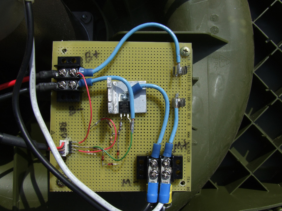
Option 3 was the obvious choice, especially because options 1 and 2 cost $100(US) and $90(US) respectively. The new and improved(?) Applied Sciences control board costs around $25(US) to build and can re-use some of the existing parts. It also has the added benefit of not being able to weld itself "ON", because it relies on an N-channel MOSFET for power switching rather than a relay. The design and construction are exceedingly simplistic. The "safety key" (a resettable circuit breaker of unknown specs. - probably 20 amp) and a fuse holder (which actually holds the safety key) were salvaged from the old control board. A four pin row of breakaway headers were found to have the proper spacing to mate with the existing connector that terminates the wires from the handle. The wires attach to the breakaway header (CONN1 in the diagram) as follows: 1 - red, 2 - black, 3 - brown, 4 - purple. The middle pin of the MOSFET was removed because the "gate" connection is made near the heatsink. Zener diodes prevent the MOSFET gate from receiving a damaging, high voltage. The salvaged circuit breaker provides over-current protection to the motor.
Is this a drop-in replacement for the original control board?
Not entirely. By salvaging the connectors from the original control board, you may be able to use it without re-wiring the handle, assuming the color coded wires are the same on all mowers. Also, this board spins down when the handle is released. There is no electronic braking.
Do I have to use the exact parts listed?
No, but make sure that the parts you buy can handle the current of a 700W motor.
- Safety is your responsibility. This project is made available for educational purposes.