

As anyone who has designed user interfaces can attest, users cannot be relied upon to interact with a device or interface in any consistent or logical fashion. With that in mind, the Video Message Kiosk has only one button. When the button is pressed, recording is started. A green LED is then illuminated above the button to indicate that recording has begun. Additionally, the LCD screen shows the status as "recording", but what do people do? They press the button again...and again...(and again). Obviously, if the camera were to start and stop every time the button were pressed, the recording process would quickly become a mess. Therefore, the button is immediately disabled after the first press; functioning not only as electrical debouncing, but "human debouncing" as well. Then there exists the issue of stopping the recording process. The user cannot be relied upon to do so, so a 45-second timer is started once the button is pressed. Near the end of the period, the LED flashes to indicate that recording will end. After it expires, recording ceases and the LED is no longer illuminated.
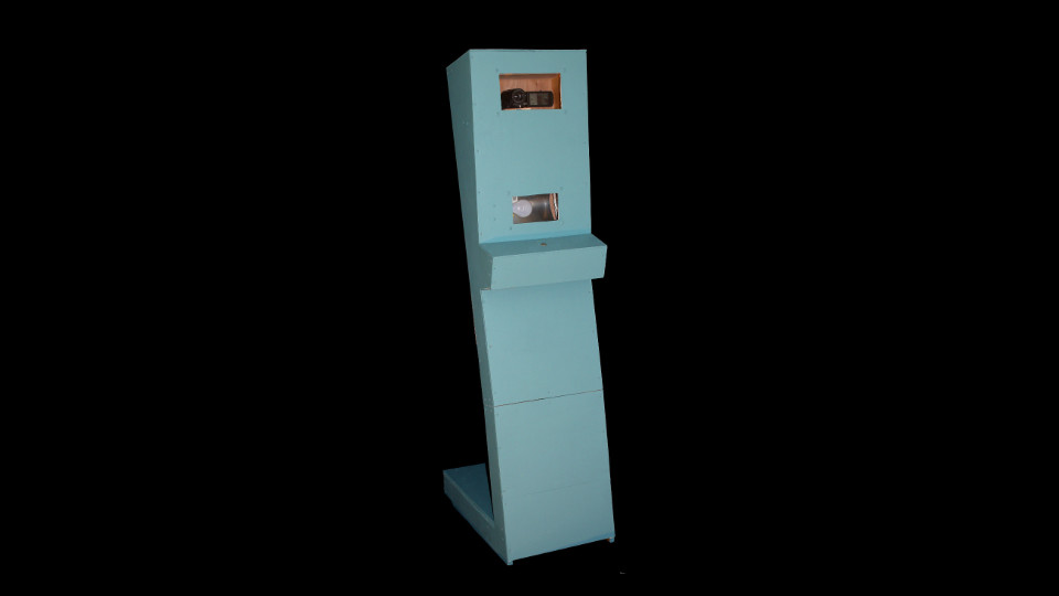
Design-wise, cost and reliability were the deciding factors in nearly all issues. Since intoxication is quite common at many events, the case/cabinet was designed not to allow people to set items or beverages upon it. The cabinet is constructed entirely of wood for easy repair. The cabinet also locks in the back to prevent anyone from stealing or tampering with the electronics. A built-in low wattage incadescent light is below the camera to illuminate the activation button and the instructions. It also provides supplemental lighting in case of poor or low lighting.
The timer, LED and camera IR trigger are all controlled by an Atmel Attiny85. The code is available above.
What cameras are supported in the firmware?
The firmware contains the code for the Canon HF-M500. Other Canon cameras with an infrared receiver may also work. Different brands will require the changing of one or more variables in the code.
How is the kiosk transported?
It disassembles into two parts which fit easily within a small car.
Why is it painted blue?
We had blue paint left from another project.
Why not include a larger/separate monitor so people can see themselves?
In testing, people stared at the monitor rather than the camera which gave the footage a strange "videoconference" feel.
Did you consider putting a digital display somewhere on the kiosk?
Yes, but a flashing LED has similar function and is less expensive.
- The original intention was to interface with an existing IR remote control, but its low-quality construction and poor operation forced a last-minute redesign.
- The most common phrase uttered during recording: "Is this recording?"
- Few people left messages in the middle-range of the time limit. They were either very short or extremely long and rambling.
- The kiosk has survived being struck with the back of a drunkard's head at least once.
- A group of people hypothesizing about how the kiosk functions speculated it "uses motors".